How to get stress tensors on edge of a shell in python results, by defining position and layer


Best Answer
-
Hi @Kev,
You need use the operator
dpf.operators.utility.change_shell_layers()for specifying the layers.0:Top, 1: Bottom, 2: BottomTop, 3:Mid, 4:BottomTopMidYou can read more about it in the DPF operator help. Below is an example code which works well. You can create custom properties (drop-down) to select the Shell-Layer and the Coordinate System.
- import mech_dpf
- import Ans.DataProcessing as dpf
- mech_dpf.setExtAPI(ExtAPI)
- dataSource = dpf.DataSources(analysis.ResultFileName)
- sx = dpf.operators.result.stress_X()
- sx.inputs.data_sources.Connect(dataSource)
- ns_op = dpf.operators.scoping.on_named_selection()
- ns_op.inputs.data_sources.Connect(dataSource)
- ns_op.inputs.requested_location.Connect('Nodal')
- ns_op.inputs.named_selection_name.Connect('EDGE')
- sx.inputs.mesh_scoping.Connect(ns_op.outputs.mesh_scoping)
- sx.inputs.bool_rotate_to_global.Connect(False)
- sx_top = dpf.operators.utility.change_shell_layers()
- sx_top.inputs.fields_container.Connect(sx)
- """
- Define Shell layer
- """
- sx_top.inputs.e_shell_layer.Connect(0)
2 - import mech_dpf


Answers
-
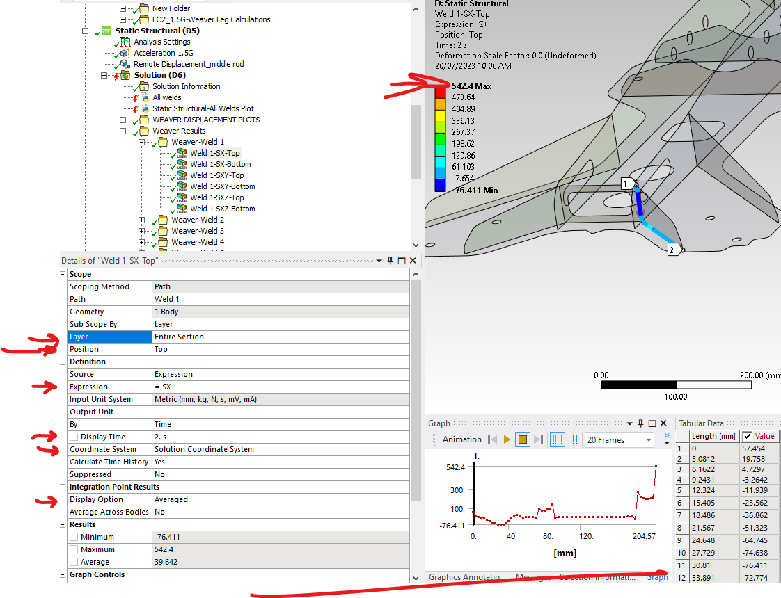
I would like to create a python result file that mimics a user plot With the populated fields as shown in the figure below:

So far this is as far as I have gone with the code below (Showing just a section of the code):
dataSource = dpf.DataSources(analysis.ResultFileName)
DisplayDict = {}
DisplayDict[0] = dpf.locations.nodal
DisplayDict[1] = dpf.locations.elemental
DisplayDict[2] = dpf.locations.elemental_nodal
GrphicsTypeDict = {}
GrphicsTypeDict[1] = dpf.enums.GFXContourType.GeomFaceScoping
#endregion
MeshScoping=MeshScopingFromNS(NS)
global TimeFreqSupport
TimeFreqSupport=GetResultsTimeData()
WriteMessage("Setup results operator")
ResultOp = dpf.operators.result.stress_X () #dpf.operators.result.stress_von_mises()
ResultOp.inputs.bool_rotate_to_global.Connect(False)
ResultOp.inputs.mesh_scoping.Connect(MeshScoping)
TimeScoping=GetTimeScoping(TimeSelectionType, Step, CalcTimeHistory)
ResultOp.inputs.time_scoping.Connect(TimeScoping)
ResultOp.inputs.data_sources.Connect(dataSource)
if Display==0 or Display==1:
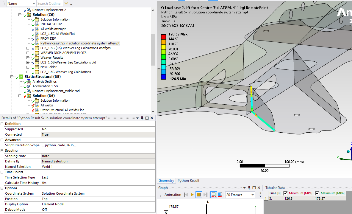
ResultOp.inputs.requested_location.Connect(DisplayDict[Display])When I evaluate this pyresult, I get a different stress distribution which tells me some of the properties are not set correctly.

Would appreciate the help with this greatly :)
Cheers0 -
Hi Ayush thanks for the help.
I did make adjustments to the code as per your instructions however I am still struggling to replicate the results of the user plot.
I have attached an archived file with my python result file and the user plot file in there. would greatly appreciate it if someone could have a look and tell me what an I missing.
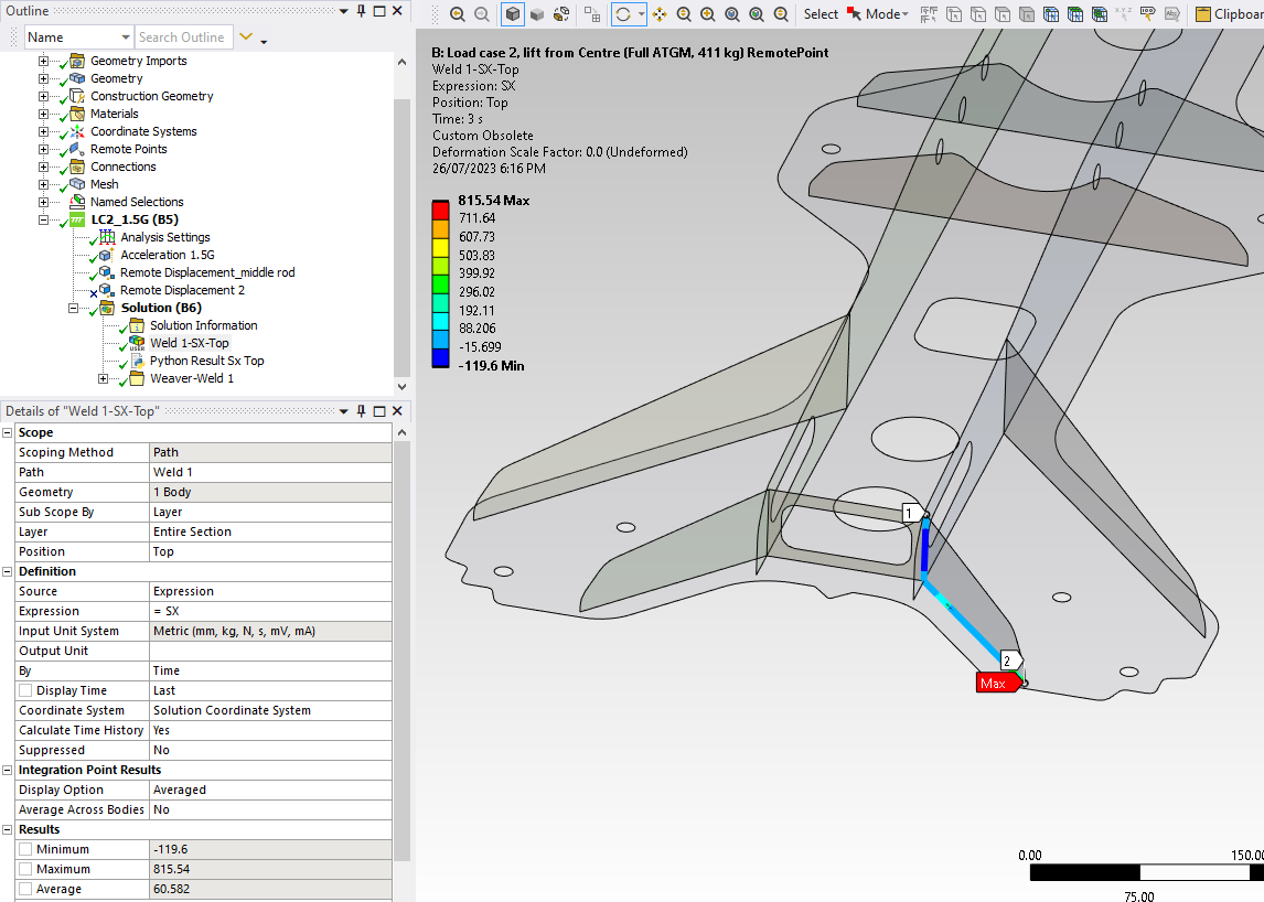
Here's the result of the user plot:
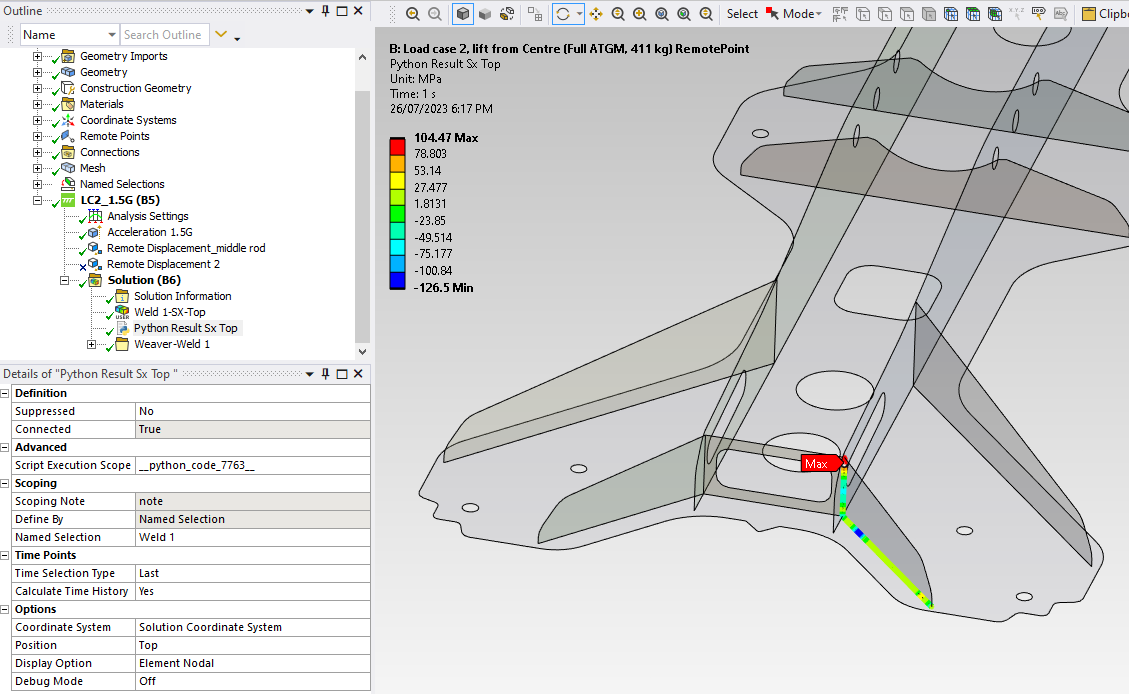
And here is what my Python result is producing:

Here is the updated code just in case. Will appreciate the help :
def define_dpf_workflow(analysis):
- #region Get the user property values
- GroupName="Options"
- CS = PropValue(GroupName+"/"+"Coordinate System")
- Position = int(PropValue(GroupName+"/"+"Position"))
- Display = int(PropValue(GroupName+"/"+"Display Option"))
- global DebugMode
- DebugMode = bool(int(PropValue(GroupName+"/"+"Debug Mode")))
- GroupName="Time Points"
- TimeSelectionType = int(PropValue(GroupName+"/"+"Time Selection Type"))
- Step = int(PropValue(GroupName+"/"+"Step"))
- CalcTimeHistory = bool(int(PropValue(GroupName+"/"+"Calculate Time History")))
- NS = PropValue("Scoping/Scoping/Named Selection")
- #endregion
- #region import standard modules
- global dataSource
- dataSource = dpf.DataSources(analysis.ResultFileName)
- DisplayDict = {}
- DisplayDict[0] = dpf.locations.nodal
- DisplayDict[1] = dpf.locations.elemental
- DisplayDict[2] = dpf.locations.elemental_nodal
- GrphicsTypeDict = {}
- GrphicsTypeDict[1] = dpf.enums.GFXContourType.GeomFaceScoping
- #endregion
- MeshScoping=MeshScopingFromNS(NS)
- global TimeFreqSupport
- TimeFreqSupport=GetResultsTimeData()
- WriteMessage("Setup results operator")
- ResultOp = dpf.operators.result.stress_X () #dpf.operators.result.stress_von_mises()
- ResultOp.inputs.bool_rotate_to_global.Connect(False) #setting to solution coordiante system
- ResultOp.inputs.mesh_scoping.Connect(MeshScoping)
- TimeScoping=GetTimeScoping(TimeSelectionType, Step, CalcTimeHistory)
- ResultOp.inputs.time_scoping.Connect(TimeScoping)
- ResultOp.inputs.data_sources.Connect(dataSource)
- if Display==0 or Display==1:
- ResultOp.inputs.requested_location.Connect(DisplayDict[Display])
- sx_top = dpf.operators.utility.change_shell_layers()
- sx_top.inputs.fields_container.Connect(ResultOp)
- sx_top.inputs.e_shell_layer.Connect(0)#0:Top, 1: Bottom, 2: BottomTop, 3:Mid, 4:BottomTopMid
- WriteMessage("Get displacement operator for showing warped model")
- u = dpf.operators.result.displacement()
- uMeshScoping=MeshScopingFromNS(NS, requested_location=dpf.locations.nodal)
- u.inputs.mesh_scoping.Connect(uMeshScoping)
- u.inputs.time_scoping.Connect(dpf.TimeFreqScopingFactory.ScopingByLoadSteps([Step]))
- u.inputs.data_sources.Connect(dataSource)
- WriteMessage("region Setup the final workflow")
- dpf_workflow = dpf.Workflow()
- GraphicsType = GetGraphicsType(NS)
- OutputContourObj = sx_top
- if GraphicsType!=None:
- dpf_workflow.SetOutputContour(sx_top, GraphicsType)
- else:
- dpf_workflow.SetOutputContour(sx_top)
- dpf_workflow.SetOutputWarpField(u)
- dpf_workflow.Record('wf_id', False)
- this.WorkflowId = dpf_workflow.GetRecordedId()
- return
0 - #region Get the user property values
-
@Kev , Looking at line 12 of your code above, I am not sure of the way you are scoping the nodes. I suggest select the edges, create a named selection, convert that into nodes and then use the nodal named selection in the scoping of the DPF code. That should give you the same results.
0 -
@Kev, I would recommend you to reach out via the standard Ansys Technical support, as this might involve model debugging and hence not a post for Ansys Developer Forum but a question for standard Ansys Technical Support. There you can even share your model and one of the Ansys Tech Support Engineers will help you debug the issue.
0